Simulation and analysis of thermoacoustic engines
Catherine Weisman, Diana Baltean, Maurice-Xavier François, Patrick Le Quéré, in collaboration with Luc Bauwens (University of Calgary, Canada), Pierre Carlès (IJLRA) and Patxi Duthil (IPNO Orsay)
Contents |
Objectives
The general scope of the study is thermoacoustic engines. A stack is placed between two heat exchangers, in a tube ending at a dead end and with a given charge (for example a thermoacoustic refrigerator) on the other side. A temperature difference is applied between the heat exchangers. From a technical point of view, there is unavoidable dead space between stack and heat exchangers. One specific objective is to study the effect of varying the spacing between stack and heat exchangers on wave amplification, and therefore on the efficiency of such a thermoacoustic wave generator.
One important hypothesis is that the stack is short compared to the resonator length, which justifies a low Mach number approximation for the flow within the stack. In this context, a 2D low Mach number computer code is modified in order to take into account the heat exchangers and the coupling between the stack and the resonator. The code was previously used to operate in the heat pump (refrigeration) configuration [1],[2], where given oscillating flow and temperature conditions at the boundaries led to the establishment of a temperature gradient along the plates. In the present study, temperature is prescribed at the heat exchangers, and the flow boundary conditions are solved so that time amplication of the wave can be analysed.
In another related study, the necessary existence of dead space between stack and heat exchangers leads to convective movements around and within the horizontal stack plates. These movements prevent the establisment of a linear distribution of temperature along the plates across the stack, which can prevent the onset of the thermoacoustic wave amplification. We have conducted numerical studies of natural convection within a differentially heated cavity containing horizontal conducting plates, under Boussinesq assumptions. This second study does not consider oscillating flow.
Description
Low Mach number simulations
Geometry
Due to the periodicity of the stack plates arrangement, if gravity effects are neglected, the domain of study can be restricted to one horizontal slice of the resonator, sandwiched between two half stack plates, containing the whole stack length, and extending past the stack (Figure 1). The heat exchangers are first considered to be ideal.
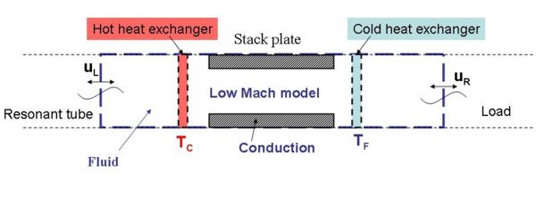 |
All frontiers of the domain are set to be adiabatic. Periodic flow conditions are set at horizontal boundaries. At the solid/fluid interface, no-slip conditions are imposed, as well as continuity of temperature and heat flux.
Model description
Let the reference length be the stack length  and the reference time be the acoustic period
  (where
  is the resonant frequency determined by the resonator length). The reference velocity is then
  , and the reference Mach number
  is a small parameter, due to the short stack assumption.
The low Mach number asymptotic development of the Navier-Stokes equations, following Paolucci's approach [3], results in decoupling the acoustic propagation and its macroscopic effect on pressure.
The pressure development  , results in splitting the pressure variable into two terms
  , where
  is only a function of time, and the dynamic pressure
  , related to
  .
The resulting equations within the fluid are the following :
.
The resulting equations within the fluid are the following :

![\scriptstyle \frac{\partial (\rho V)}{\partial t} + \nabla .[\rho V x V]
= -\frac{1}{\gamma} \nabla \pi + \frac{1}{Re}\nabla .\tau](../upload/math/5/9/c/59c72728eeb48d35e44db7b5a9f426f1.png)
![\scriptstyle \rho c_p [\frac{\partial T}{\partial t} + (V . \nabla)T ]
= \frac{1}{Pe} \nabla . (k\nabla T) + \frac{\gamma -1}{\gamma}\frac{\partial \overline{P}}{\partial t}](../upload/math/b/e/e/bee4d002f57079ea4adf3f601170f0ea.png)

with ![\scriptstyle \tau = \mu [\nabla V + (\nabla V)^t - \frac{2}{3} (\nabla . V)I]](../upload/math/4/f/1/4f174b9c7c952c1b0191a5a9371a76b2.png)
These equations are written in a nondimensional form. The density  , thermal conductivity
  , specific heat
  are referenced with their values taken at a given reference temperature
  .
The Peclet number and Reynolds number are respectively defined as
.
The Peclet number and Reynolds number are respectively defined as  and
and  .
.
Due to the splitting of the pressure term, an additional energy balance equation is required for system closure :
![\scriptstyle \frac{\partial \overline{P}}{\partial t} = \frac{\gamma}{\overline{\Omega}} \overline{P} [u_L - u_R + \frac{1}{Pe} \int_{\partial \Omega_f} k\nabla T . n dS ]](../upload/math/c/2/e/c2ecfadb23c23eb1860da31076242e4d.png)
In the solid plates, there is heat conduction and the equation reads

Outside the domain, a simple acoustic standing wave model is assumed. The distance between the left end of the resonant tube and the left boundary of the domain is  , and the distance between the load and the right boundary is
  . A relationship can then be written to link the velocity components at vertical domain boundaries to their values at some previous time, and therefore take into account the acoustics in the resonant tube. At each time step, it is then possible to solve for a system of three nonlinear equations governing
  ,
,  , and .
An initial temperature distribution is imposed, as well as an initial perturbation of the horizontal velocity components , at the vertical boundaries, and of the mean pressure in the stack . We then expect to observe the wave amplification,  ,
,  and
and  . Numerical tests are currently in progress.
Boussinesq simulations of convection before onset within the stack
Geometry
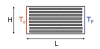
The model geometry introduced for this study is a two-dimensional rectangular cavity, partially filled with a stack of parallel plates (Figure 2). This is a simplification from the complete geometry where the stack of horizontal plates fills one of the cylindrical tubes making the resonator. Also, the heat exchangers are modelled here as vertical walls set at a given distance of each end of the stack plates, and given constant temperature is assumed on each wall ( is the imposed temperature difference between the two walls). The horizontal boundaries are adiabatic, which is a reasonable despcription of the experimental setup, where large efforts are made to insure as few losses as possible through the outside envelope. The aspect ratio (length/height) of the cavity is fixed to match the application (equal to 2.5). The stacks used in large thermoacoustic systems consist of hundreds of plates, and Rayleigh numbers (based on the height of the cavity and the thermophysical properties of the fluid) can vary between
  and
and  . The spacing
  between the plates and their thickness
  are fixed based on the thermophysical properties of the fluid : the porosity
  is an important design parameter. Also, the thermal conductivity, density ,and heat capacity values for the conducting plates are taken into account.
 |
Because of the large number of plates, a complete computation on the actual geometry would require a very refined mesh. The adopted numerical approach consists in solving the Navier-Stokes equations written under Boussinesq assumptions for a limited number of plates. This is done using a commercial software (FLUENT VI) as well as a self-written code. In the latter, the equations are made dimensionless using H as unit length,  as reference velocity, where
  is the fluid thermal diffusivity and
 is the Rayleigh number (
 ) and
) and  as unit temperature difference.
Computations are carried out for several Rayleigh numbers between and and the number of plates is varied (17, 34, 68), keeping the porosity  constant. Results are compared for both computer codes, and a mesh convergence study is carried out (meshes of 512x512, 1024x1024, 2048x2048 and 4096x4096 grid points are considered). The final goal is to obtain a simplified model for the prediction of the temperature field, for example a homogeneized description of the stack thermophysical properties.
Results
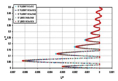
Calculations show that depending on the number of plates and the Rayleigh number, the macro convective flow can be associated with convective flows localised between plates. The example shown in Figure 3 is the case of 17 stack plates,  . The vertical profile at mid length of the stack (only a half profile is shown on the Figure) of the horizontal velocity component is shown for comparison of the codes solutions (Fluent and self-written code) for several meshes (512x512 to 2048x2048). On this example, the flow in between plates located at mid-height of the stack is similar to the convective flow is a thin and long horizontal cavity. On the contrary, the flow in between plates located near the bottom (or top) of the stack is similar to a Poiseuille flow.
 |
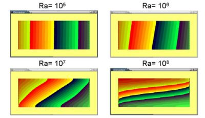
The corresponding temperature fields shown in Figures 4 for four values of the Rayleigh number suggest (by comparison with published results [4]) that a model of convection through a rectangular porous cavity (with thermophysical properties yet to be specified) could be used efficiently.
 |
Prospects
The Low Mach number simulations of thermoacoustic engines are still in progress. This will eventually provide a numerical prediction tool for optimizing the distance between heat exchangers and stack in order to obtain more efficient onset of thermoacoustic wave generators. Similarly, the simulations of convection within the stack will be a useful prediction tool for technical applications.
References
[1] P. Duthil, C. Weisman, E. Bretagne, M.-X. François, Experimental and numerical investigation of heat transfer and flow within a thermoacoustic cell, International Journal of Transport Phenomena, vol. 6(4), 265-272 (2004)
[2] P. Duthil, Etude du pompage de chaleur thermoacoustique : approche numérique et expérimentale, Thèse UPMC, (2003)
[3] S. Paolucci, On the filtering of sound from the Navier-Stokes equations. Sandia National Laboratories report SAND82-8257 (1982)
[4] V. Prasad, F. A. Kulacki, Convective heat transfer in a rectangular porous cavity - effect of aspect ratio on flow structure and heat transfer, Journal of Heat Transfer, vol. 106, 158-165 (1984)
Links
Accueil > CORO >> CORO:Page_12