TSF: oscillating fluid
Contents |
Experimental investigation of frequency response of loudspeaker-driven oscillating fluid
F. Jebali, G. Defresne, in collaboration with P. Lotton (LAUM, Le Mans)
Objectives
We report new measurements on the acoustic pressure by using a simplified system consisting of an electro-dynamic acoustic source coupled with a resonator and a heat pump stack. Previously, we have mainly studied the amplitude of the transfer function  between two acoustic pressures in oscillating flow. In the present work, we suggest in particular, to investigate the phase of this transfer function. The interest of this work is double: from the fundamental point of view, we report new simultaneous measurements of the amplitude and the phase of and then check the general aspects of the network theory of oscillating flows. From the applied point of view, both acoustic velocity measurements in oscillating flows by hot-wire anemometer technique, which presents the advantages of simplicity and low manufacturing cost next to those of PIV and LDV, and acoustic power measurements in thermoacoustic systems should be performed by controlling calibration of both amplitude and phase of acoustic pressure and velocity [1-2].
Description
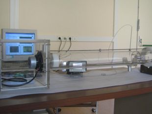
A schematic representation of the experimental set-up is shown in Fig. 1. This apparatus consists of a resonator of an adjustable length (837 mm in the present work) and 110 mm inner diameter in which is inserted a parallel plates stack. The stack was made of Mylar plates with 40 mm length, 0.25 mm thickness and 1 mm spacing. This system was driven by an electro-dynamic AP130M0 loudspeaker connected with a wave generator and loaded on its rear side by a cubic cavity of 270 x 270 x 270 mm dimensions. The oscillating pressure was measured by two prepolarized pressure-field ¼ – inch Microphones - Type 4944A laser welded to two channels DeltaTron preamplifier and flush mounted at the entrance and the end of the resonator respectively.
 Figure 1: Schematic diagram of the experimental set-up |
 |
Theoretically, the system can be regarded as combined network elements: acoustic compliance of the source cavity, mechanical and electric impedance of loudspeaker, input acoustic impedance of the front load (resonator and heat pump stack). The network model which takes into account the wave propagation character in an oscillating flow and, particularly in thermoacoustic systems, has been described in literature [3-4]. In previous works, we presented many results on acoustic pressure amplitude and the comparison of the experimental results with the analytical predictions using this model has shown a rather good agreement. However, dispersion of phase measurements prevented the comparison. So, in this work, we focus our attention on the oscillating pressure phase measurements. The model is slightly modified in the present investigation in order to take into account the coupling between the sound source and the acoustic cavities by calculating the source flow given by
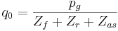
where  and
and  are the input acoustic impedances, respectively, of the front and rear cavities,
  and
and  are, respectively, generator pressure parameter and the acoustic equivalent impedance of the source which depend on electrical, mechanical and acoustical parameters of loudspeaker [4].
Results and prospects
Typical oscillating pressure measurements made by microphones 1 and 2 are reported in figure 2 for three frequencies, f = 20 Hz, f = 100 Hz and the resonant frequency fres = 215 Hz.
 Figure 2-a: f = 20 Hz |
 Figure 2-b: f = 100 Hz |
 Figure 2-c: fres = 215 Hz |
As it could be expected, these results show that, at the resonance, pressure amplitudes measured by the two microphones are maximum and their ratio tends towards unity. On the other hand, for those frequencies, pressure at microphone 1 and microphone 2 are, respectively, 0°, 90° and 180°out of phase.
One can summarize the results by investigating the transfer function (or the frequency response) between the microphones ( is defined as the ratio of the acoustic pressures which are two complex quantities). Globally, in the whole frequency range, present results show similar behaviors between calculations and measurements both in amplitude and in phase (figures 3-a and 3-b). However, we notice that experimental results on the phase disclose a non total standing wave character since the phase shift between the two pressures could be different from 0° and ±180° within some frequency ranges even though calculations show a high Standing Wave Ratio (SWR). In addition, the experimental phase value changes from about –180° to about +180° at the resonant frequency (215 Hz) when the model predicts this transition at a lower frequency. These discrepancies could be reduced by a better adjusting of some parameters (mechanical and acoustical loudspeaker parameters, effective resonator length, stack plates spacing, etc).
 Figure 3-a: Amplitude of H12 as a function of the frequency |
 |
Conclusion
In conclusion, this work shows some progress in acoustic pressure investigation and, particularly, in phase measurements by using an electro-dynamic loudspeaker as acoustic wave. The above results are general and help to a better understanding of general aspects of both oscillating flow and thermoacoustic theories. The importance of this problem, in particular the accurate prediction of pressure amplitude and phase simultaneously, clearly merits more experimental and theoretical work.
References
[1] F. Jebali, G. Huelsz : « Acoustic velocity measurements in oscillating flows » Rapport Scientifique CNRS-LIMSI, 2005.
[2] F. Jebali-Jerbi, X. Zhang, M.X. François and F. Guo : "Influence de la fréquence sur la puissance acoustique à l'entrée du régénérateur utilisé dans un réfrigérateur thermoacoustique" XVème Congrès Français de Mécanique, Nancy, 3-7 Septembre 2001.
[3] F. Jebali, J. V. Lubiez and M. X. François : "Response of a thermoacoustic refrigerator to the variation of the driving frequency and loading". International Journal of Refrigeration, 27, pp. 165-175, 2004.
[4] H. Bailliet, P. Lotton, M. Bruneau and V. Gusev: “Coupling between electrodynamic loudspeakers and thermoacoustic cavities” Acustica – acta acustica, Vol. 86, pp. 363-373, 2000.